Thursday, June 01, 2006

ITTROV - Video

The video is uploaded.

Two links are:

http://s18.photobucket.com/albums/b118/Fetichet/ITTSub/?action=view&current=ROBOT.flv
or
http://www.yousendit.com/transfer.php?action=download&ufid=83261F0C309AB188

Thank you Ronnie for encoding and uploading it.


The complete photo set (including some not seen in this blog) is available here:
http://s18.photobucket.com/albums/b118/Fetichet/ITTSub/

With the final presentation photoset here:
http://s18.photobucket.com/albums/b118/Fetichet/ITTSub/Sub2/

Wednesday, May 31, 2006

ITTROV - Conclusions and Recommendations

Conclusions and Recommendations

Structural Design and Integration (Tom Gros)

Overall, in terms of structural performance, Project ROV-ITT functioned better than I personally anticipated. It was surprisingly buoyant and maneuverable in the water considering its weight and lack of aerodynamic design.
My primary concern from the onset was the shear weight of the ROV would simply sink it with no chance of maneuvering or surfacing. I reached this conclusion due to fact that the buoyancy of the watertight case was rated at 1.5 lbs. The craft, at 7.5 lbs, far exceeded that rating. Not only did the ROV not sink when it was introduced to the water—it floated to the point where it became necessary to drill holes into the PVC frame in order to provide ballast. In my initial determination, I did not take into consideration the astounding buoyancy of PVC. With the frame now taking on water, all that was required to operate the craft was to add a few pieces of Styrofoam to trim the position of the ROV—that is to position it horizontally in the water.
As far as maneuverability is concerned, the ROV also exceeded my expectations, barring two issues—surfacing and veering left while moving forward. The problem of surfacing was not completely resolved even when a second bilge pump was dedicated to the effort. At a certain depth, the water pressure was simply too great to overcome. In my mind this issue could be overcome in one of two ways. The first would involve a pressure sensor that would automatically turn on the bilge pumps responsible for upward thrust when a critical depth was reached. The second solution would entail replacing the impellers built into the bilge pumps with external propellers designed for thrust.
The fact that the craft consistently veered left, despite our best efforts to rectify the situation, is undoubtedly due to the total disregard to aerodynamics in the design. The solution may lie in the attachment of a bow to the frame—although this may create an unacceptable amount of drag. Electronically, the resolution might be more achievable. If there were a way to control the speed of each motor individually, the veering could easily be eliminated.
Perhaps, the biggest disappointment was the amount of leakage that occurred. Although water penetration could have occurred in any of the six ports used to route wiring into the housing, in my mind, the most likely culprit is the case itself. Although the manufacturer claims that the case is waterproof, it is designed to keep electronic equipment dry in cases of accidental exposure to water. Our application required prolonged exposure not only to water, but also water pressure since the ROV was intended to remain submerged for extended periods of time. Any future applications of this design would have to address this problem.


Software and Electronic Design for ROVITT (Emery Premeaux)

There is plenty of code space and I/O left on the PIC for more features. Using the standard ASCII character set for command input leaves a lot of room. For instance, the operator could press‘t’ to get back water temperature. Capital T could return a second temperature, or something else. P might request a pressure reading. In addition, the PIC has a built in timer, so it could be set up to automatically send information, sort of like a heartbeat. It could respond every two seconds with a temp and pressure message. To continue with the heartbeat analogy, the topside software could be written such that if this message is not received on time, a warning is displayed indicating that the ROV is not in communication.
Other features might include a water temperature sensor and a depth gauge. Another idea might be a device similar to an aerometer to gauge the speed of the sub. Perhaps a leak detector could be included to warn the controller of water intrusion.

ITTROV - Software

Software Design for ROVITT (Emery Premeaux)


The software design for the ITTROV project was a challenge. First and foremost was to categorize how the software should work. This plan would guide the rest of the design process. Unfortunately, it changed constantly as I re-evaluated what was important, and what was not.
I wrote the PIC microcontroller’s code in C, using HI-TECH’s C compiler with their HI-TIDE Integrated Development Environment. The version I used is free to all, and will compile code for a select few PIC chips. I found that after working with the system for a while, I became very comfortable with the IDE and compiling structure. The C programming classes we took in the Bachelors program were very helpful.

In order to get the code onto the PIC chip, I used a programming device called the PICALL. It is connected through the parallel port and has its own software to load up the compiled program and burn it into the PIC.

The final step for the PIC was to return it to a prototyping board I had set up that replicated the circuitry still under construction for the ROV. The board had a clock circuit, a power supply, and the same MAX232 communications chip as the sub would have. The only difference between the test board and the real thing was that the motor outputs on the test board were LEDs rather than the motor driver circuit.

I had decided early on to design the code on the PIC in such a way as to allow the user to operate it from a serial communications program such as Terminal. This meant that all of the commands to and responses from the ROV would be human readable. I wanted the user to be able to enter a command, and the sub would respond back with text confirming the action.
The final system would allow for a separate program written in Visual Basic to control the ROV. This program would connect to the com port of the ROV and act as if it were human. It would read in the responses from the ROV and display status messages on the control panel. When the operator clicks on a command button, the software would take care of sending that command and verifying the ROV received it properly.

The software went through several revisions. The first idea was to accept commands in a string format, such as “1 100.” This would indicate motor one should be operating at 100%. Unfortunately after many days of scratching my head, I found out that the free version of the HI-TECH C does not include string INPUT functions. However it did include string OUTPUT functions. This is important because it meant I could make the sub respond back with a message like “Motor 1 at 100 percent” but I could not take in the command in the first place. In fact, all I could process in was a single character.

The final version of the revision code worked more like a conversation with the ROV. It went something like this:
Enter a Command: 1
Enter a value for motor 1: 1
Motor 1 is ON.

This worked out well, at first. While still building the electronics and integrating them to the frame it was helpful to be able to operate single motors at a time. After a while problems began to surface.

The first problem was that the code executed a sort of timed loop through the nested Select Case statements that made up the code. It expected the commands to occur at specific moments, and could not deal with them when entered at the wrong time. This often led to multiple tries re-entering the commands in the Terminal program. It was also very clunky to try to move the sub around. We need to turn on combinations of two motors. There would be a long time delay between getting both motors to turn on.

It was felt that the interface software on the laptop would alleviate this somewhat. It was being developed in parallel with the PIC code. I had to create needlessly complex code to deal with this ‘conversation delay’ between the PIC and the computer. To make things worse, I had to analyze the responses back from the PIC in order to determine when it was acceptable to send commands.

In order to get around some of this, I wrote the code to use subroutines. For example: Clicking on the ‘forward’ button would call two functions. Each motor has an “On” and an “Off” function. So “forward” would call the “on” functions for the appropriate motors. Each motor function then sets two variables: the motor number and the value (1 for on, 0 for off). This function then calls a final function to communicate this request to the ROV.

This isolated my problems communicating to only one section of code. After working on this process for a long time, I still could not get around the problems with the ROV. There would still be long delays between getting two motors on, if the second motor command ever even managed to get there. The whole deal was unreliable.

It was time for plan B. I had no plan B. It was 3 weeks to the presentation and I had no idea how to fix this. Eventually it came to me while no where near a computer. The design constraint of HI-TECH C was that I could only send one character at a time. So, why bother sending multiple characters to get anywhere?

I completely redesigned the ROV software with only one Select Case process. It now accepted u, d, l, r, f, b, and s. Up, Down, Left, Right, Forward, Backwards and all Stop. I then set all motors appropriately to the command sent. For instance, Up and Down will not affect the other navigation commands, and those commands will not affect Up and Down. However, when Forward is sent, all motors not intended for that command are turned off. This meant that I could only turn in place and not turn while moving forward, but it vastly simplified both sides of the code. The loop also ran much quicker. The ROV was not asking for commands in a timed manner, and accepted them at any given moment.

It was a joy to see my motor LEDs respond instantly to my requests. I was so happy in fact that I placed personality into the responses the ROV gives when it processes a request. For instance, when ‘f’ is sent, the ROV may with “Forward! Aye, aye, captain!”

ITTROV - Frame construction

Tom describes his process of designing the frame:

Structural Design and Integration (Tom Gros)


The final design agreed upon for Project ROV-ITT was a 9 inch x 9 inch x 12 inch frame structure made of ½-inch PVC. Preliminary plans did not include a frame structure at all. Instead they called for the electronics of this project to be housed in everything from capped 3-inch PVC pipe to garden spray canisters. Each option was eliminated one-by-one for various reasons. For example, the option of using a garden sprayer was eliminated because, although it would be large enough to house all of the components and easily waterproofed, the opening was too small to mount the components. Generally, options were eliminated for one or more of the following reasons:
Access to the circuit board would have been difficult or even impossible.
The craft would not have been able to be sealed or resealed.
Securely mounting the bilge pumps without jeopardizing the structural integrity of the craft would have been implausible.
Waterproof routing of the power cables and umbilical to the craft’s interior would have been an issue.
Camera placement would have required the integration of a watertight lens.

Even the PVC frame underwent several design changes. During the first week, we discussed, as a group, different options for the frame’s construction. We concluded that, by mounting some of the components such as the lights, on the outside of the craft and locating others, like the battery, to the surface, a small, light-weight and watertight case would be the perfect option to house a circuit board and camera. The frame would therefore be constructed around the case containing the “brain” of the craft. The initial version was laid out and measured on a two-dimensional plane which resulted in the prototype being oversized and cumbersome—approximately twice the size of the final version. I determined the final design by removing half of the structure and rearranging the placement of the components to be integrated into a more efficient configuration.
The next major challenge consisted of mounting the case used to house the circuit board and bilge pumps used for propulsion onto the frame. The main problem in this endeavor was the fact that both pump housing and PVC frame are round. Merely attaching the pumps to the frame by means of wire ties provided no stability—causing the pumps to slide around the frame when producing thrust. One solution that I quickly eliminated was to dismantle the pump in order to attach the frame by means of bolts. The reason this option was eliminated was the fact that, considering that there are six pumps, this would have been too time consuming and there would be no guarantee that the problem would be solved. Rather, I decided upon a more efficient solution. It was much simpler to attach a floor to the frame to which the pumps could be mounted securely. The materials I decided on to construct this floor were plastic gutter screens and lightweight metal truss ties used to provide stability. The truss ties were also decided upon to be used as mounts for the plastic case.
The remainder of my involvement to this project, until the first test run, consisted of the construction of the umbilical cable and mounting the camera. The umbilical was constructed by zip-tying a section of Cat-5 cable, used for video transmission, to RG-45 cable, used for vessel control and power. Since the watertight case contained a clear lid, mounting the camera was easily accomplished by simply attaching it using double-sided tape. I also completed the final integration of the bilge pumps to the frame. The remainder of my time consisted of helping Ronnie with the integration of the electronics to the structure of the craft. This included routing the wiring from both pumps and umbilical through hose barbs screwed into 6 holes we drilled into the case housing.
The initial test run identified two problems with the structural design of the craft: It was unable to move forward in a straight line and the bilge pump responsible for upward movement did not provide enough thrust to allow it to surface. Emery and I repositioned the pumps to a horizontal rather than vertical orientation in an effort to stabilize them, allowing the craft to move forward without veering to the left. The pump intended to provide downward thrust was remounted to help resolve the lack of surfacing ability. The repositioning of all six pumps also allowed for the remounting of the case from a diagonal to a horizontal alignment, reducing drag and, theoretically, further addressing the veering problem. Other than these two issues, the design merely required some trimming to level its position in the water.


(note: Tom mixed up his cables! The Cat 5 sends power and RS232 data, while the RG-45 sends video.)

ITTROV - Electronics


Ronnie does a good job explaining all the technical details to the circuitry:

Circuit Design and Build


After deciding to use the Rule 360 GPH (gallon per hour) bilge pumps as our source of movement for our under water ROV, the next step was to design and build a circuit board that would be able to switch these pumps ON and OFF.
Since we are going to have a total of six pumps, two for forward, two for reverse, and two for surfacing we would need six switching circuits. Each circuit would control a pump of its own. We also wanted to implement a light that could be turned ON and OFF, but time and resources prevented us from completing that task. With the six pumps and light, we ended up building a total of seven switching circuits.
The Rule bilge pumps could potentially draw up to 3 amps; this was a problem because we were using a PIC16F877 microcontroller. This microcontroller can only source a few hundred milliamps, which is much too small. So the question was “What can we use to switch ON and OFF a large current?” Our answer to this was the TIP 107. The TIP 107 is a Darlington transistor pack, which means it is made up of two other transistors. With a heat-sink the TIP can handle up to 5 amps. This was perfect for the pumps.
However, we still couldn’t drive the base of the TIP with the micro-controller, there was still too much current draw on the PIC. To get around this, we biased the TIP with two resistors. We used a 1k-Ohm and a 10k-Ohm resistor in series creating a voltage divider. The resistors were able to handle the current needed to forward bias the TIP.
Now that we had the TIP in the ON position, we needed to be able to turn it OFF and then ON again. To accomplish this we used a 2N2222 transistor. The PIC can easily turn this ON and OFF, and in turn it will connect the voltage divider to ground, thus turning the TIP OFF and ON again. We also added a 470-Ohm resistor between the transistor and the PIC, this was to limit the current and protect the PIC from burning out.
We did run into a small problem after building our motor circuits. When we tried running the motors, instead of being able to switch a motor ON or OFF, they all ran constantly. We checked our solder joints and grounds, but everything looked to be okay. After we double checked our data sheets we finally realized that we had mixed up the collector and emitter leads on our TIP107 transistor. This was causing the current to flow constantly, which was why we weren’t able to switch the pumps ON and OFF. A quick solder job and a re-test, and everything was working as planned.
Now, to make the PIC work we had to use a CTX 155 crystal oscillator. This acts as the clock pulse for the PIC and runs at 4 MHz. We also used a 7805 Voltage regulator. We took a 9 Volt power supply that would run our external camera, and used it to power the 5 volt regulator at the same time. This meant we had 9 Volts going to the camera and 5 Volts going to the PIC.
The last chip we used was the MAX-232, this is a Maxim RS232 level shifter. Because the laptop’s serial port is a differential output, it uses positive and negative voltages to make the signal. However, the PIC chip is a TTL RS232 and can only handle 0 Volts or 5 Volts. The MAX chip converts them so that they can communicate without blowing things up. We chose this version because it required no external capacitors and would keep things much simpler.
The PIC chip is a microcontroller and has a built in EEPROM (Electrically-Erasable Programmable Read-Only Memory) and program memory. This made it easy to reprogram when necessary. It also has an 8-bit processor with 5 I/O ports.
After many hours of designing and soldering our circuit board was complete. We had seven switching circuits, six of them to run pumps, and an empty slot for a wildcard. Something like a light or emergency surfacing balloon could be implemented. There was also a voltage regulator to control the PIC and an external camera. The MAX 232 enabled us to communicate with a laptop, and the CTX 155 oscillator helped the PIC run smoothly. The rest was up to the software and mechanical development.
The PIC chip has a lot of free code space and open port pins for extra features. Features we would add include a water temperature sensor and a depth gauge. Another idea might be a device similar to an aerometer to gauge the speed of the sub. Perhaps a leak detector could be included to warn the controller of water intrusion.

Tuesday, May 30, 2006

ITTROV - Presentation day

Just a note, all posts in this blog are reverse chronological order. (i.e. the first post is on the bottom, with the newest posts on top. So, you see the end results before seeing how it got built.)

The photos of each post are not in any particular order.

On to the presentation day photo-book:


This would be the final design of the sub. We put some pretty stickers made by Tom to accent it. Notice the umbrella on the electronics case (my favorite!)

The Case is open to demonstrate easy access to the electronics. The frame pops apart so that the top (electronics) and bottom (thrusters) could be layed side by side.


Were about to start, and apparently in good spirits.

I (middle) did the opening presentation, Tom (sitting) presented the mechanical design, Ronnie (left) spoke about the electronics, I finished up with software, and Tom came back to talk about the challenges we met, the ones we didn't, and what could be done to correct the problems. We all spoke about enhancements that could be made.


After that, it was up to judge questions and a short demonstration.


Mr Toussant looks on as I set up the demonstration.


I'm talking about software design here. Its hard to make a powerpoint about software code. So instead, I left up Ronnies electronics slide, and was able to use it to describe how the software in the PIC interfaced with the outside world.


I suppose this is part of the post presentation demonstration.


The team (L to R): Tom Gros, Emery Premeaux (me), Ronnie Trinh, and instructor Mr. Toussant.


Sunday, May 21, 2006

ITTROV - Water test


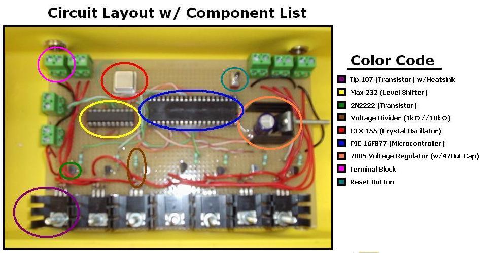
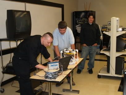
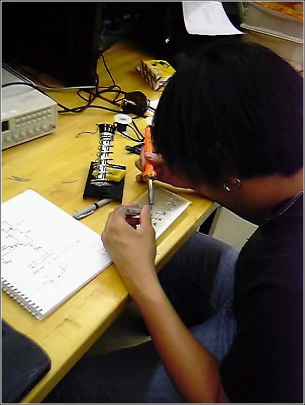
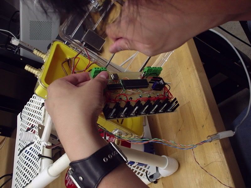
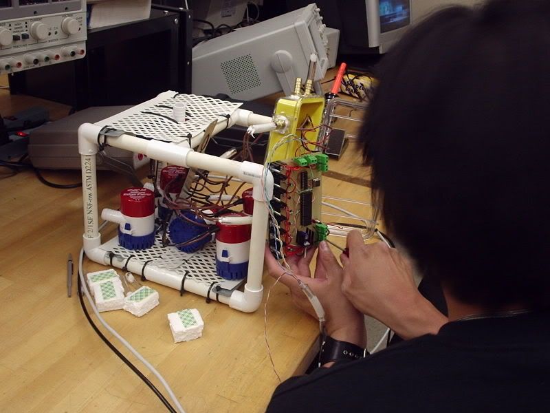
Ronni puts the finishing touches on the board. We had to rewrite the PIC code a few times to get things right.

We also modified the body after a an initial water test made it clear that the sub would not sink and surface. We placed the electronics case horizontally so the sub would trim better in the water. We also set the pumps so that we have two downward facing pumps instead of one up and one down. The sub sort of puddle hops.


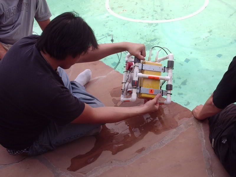
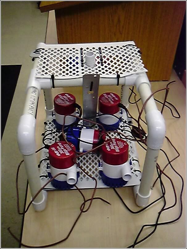
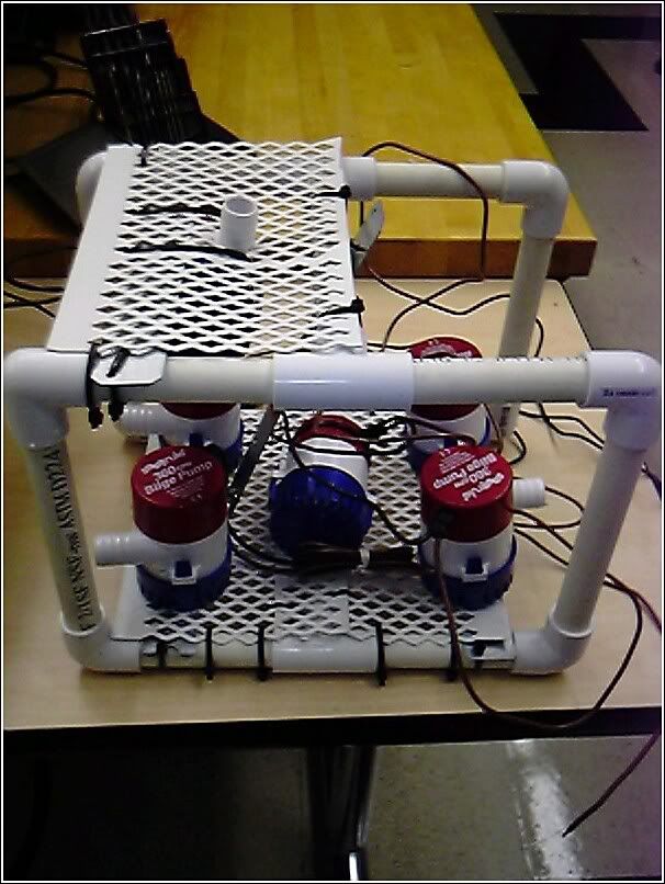
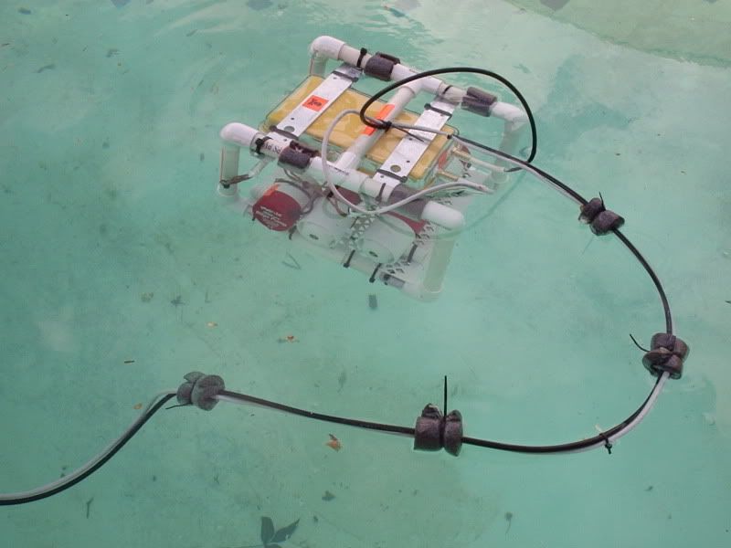
Top view of the sub shows the 4 pieces of pipe foam used to help maintain boyancy for the sub.
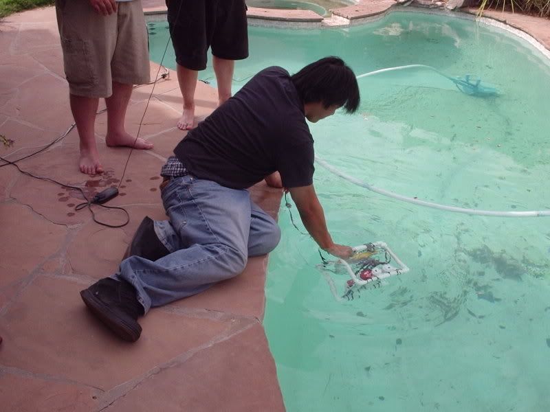


About to get wet...


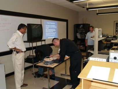
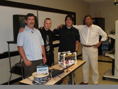
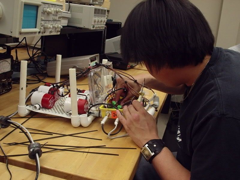
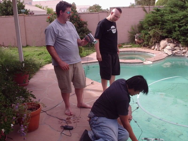
The whole team. Final troubleshooting. We had a a bit of a leakage problem, but overall the sub performed well.


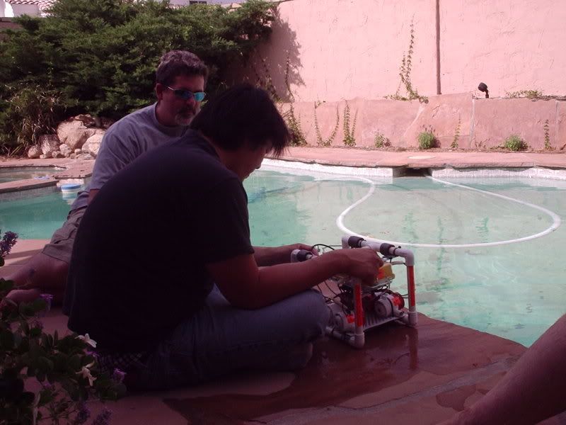
The sub is in the water. The original design was in the water the previous week, and required more trim material to keep it stable. The yellow electronics box was originally vertical. With it laying flat, it is a lot more stable, and moves through the water quicker.


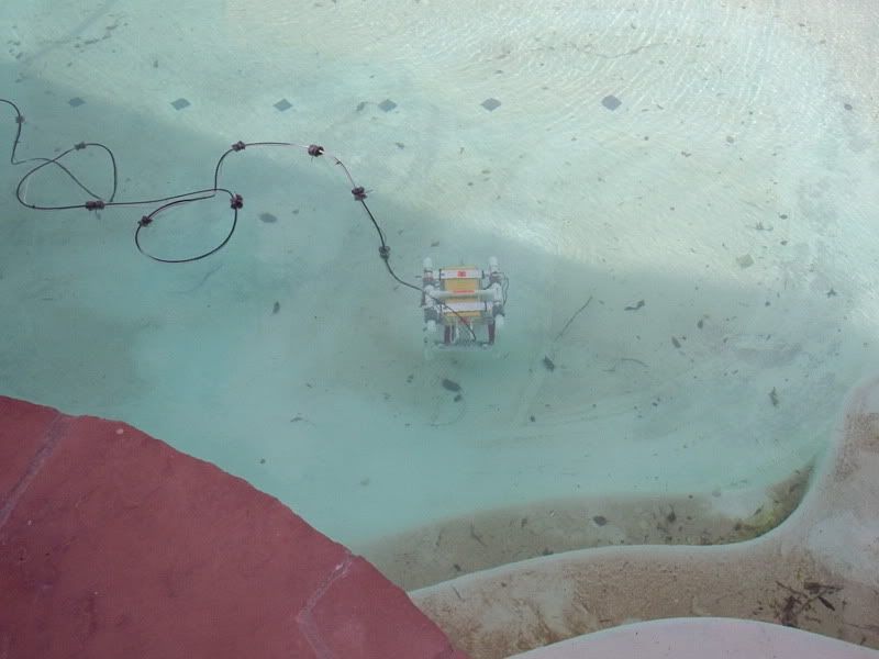
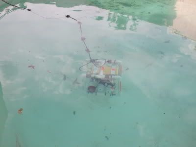
Here you can see the sub sliding around the bottom of the pool. We got sucked over to the drain at one point.


Tom is serviceing the power and communications cable, so as not to get us tangled up with the Pool's cleaner hose.


I SWEAR I was not hung over in this shot! ;)
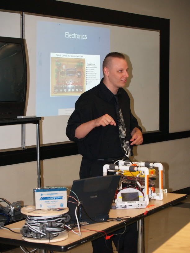
The laptop runs a small program written in VB to send commands to the sub.

The sub can also communicate directly with any serial port. It accepts simple one charactor commands to perform all of its functions, and responds back to verify that it accepted the command.


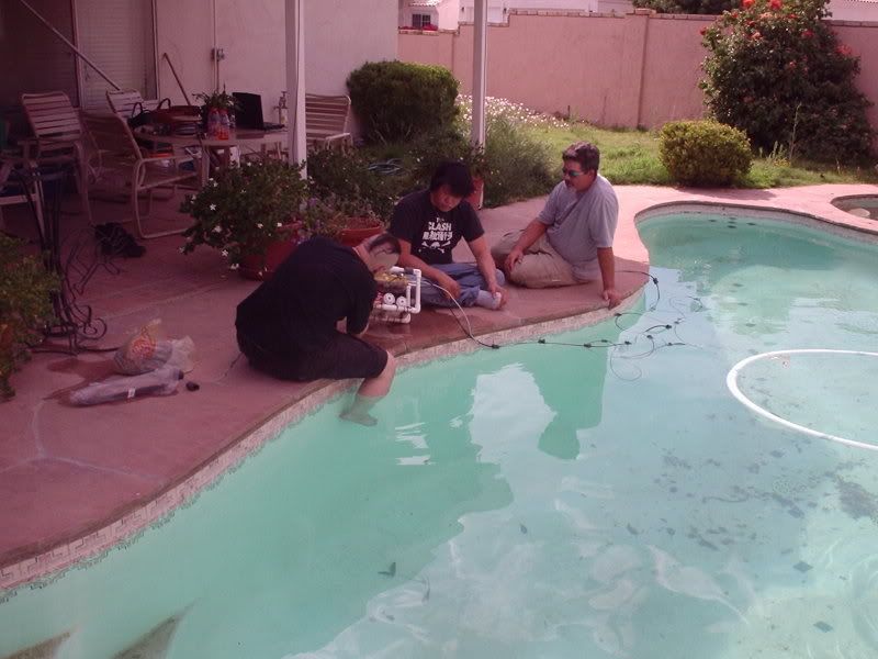
The sub is just below the photo here. We have to tilt the sub in several directions when putting it in the water. The frame of the sub has several holes in it that are used to fill the frame with water, so as not to have an affect on the trim of the sub. Trim is how the sub sits and floats [or sinks] in the water. Trim is in effect, how we control boyancy in the water. We are using passive trim (foam and the floating of the electronics case) as opposed to active trim (flooding tanks).


Once nearly neutrally boyant, the sub becomes very light in the water. It is quite heafty out of water and at first there was much concern about it sinking like a rock, and the thrusters never moving it.

After dumping it in and flooding the frame, however, a little push goes a long way.


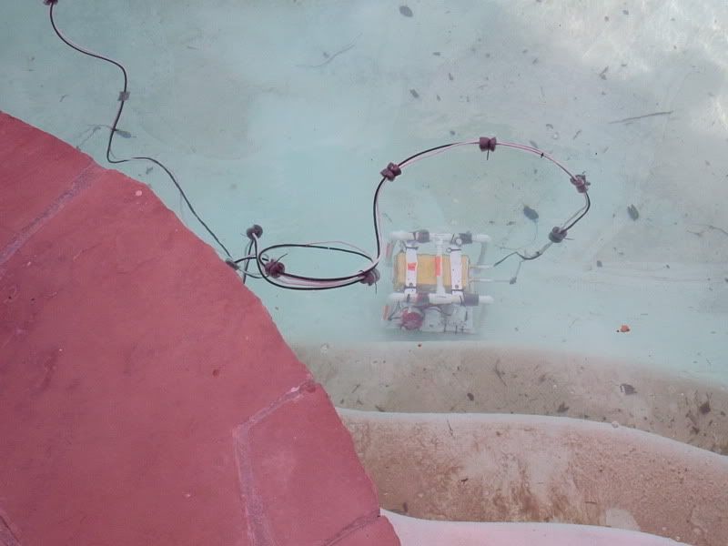
A good shot of the sub and its umbilical. Those little squares are more foam tied to the cables. The reason for that is to keep the cable boyant as well. If it were not boyant, it would fall to the bottom and drag the sub down with it. If it is too boyant, it would float only on the surface and keep the sub from diving when we want it too.


Another sub and cable shot. You can see how the cable snakes around as parts of it float and parts of it sink.

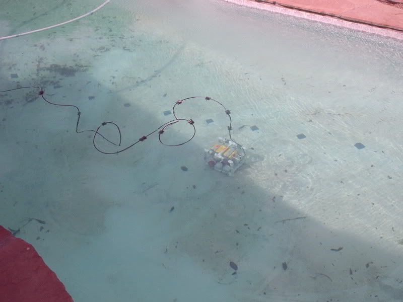
The pools tile triangles were usefull in the video footage to tell that the sub was in fact moving around.


Gratuitous sub and cable shot!


Fish out of water.
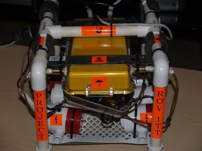
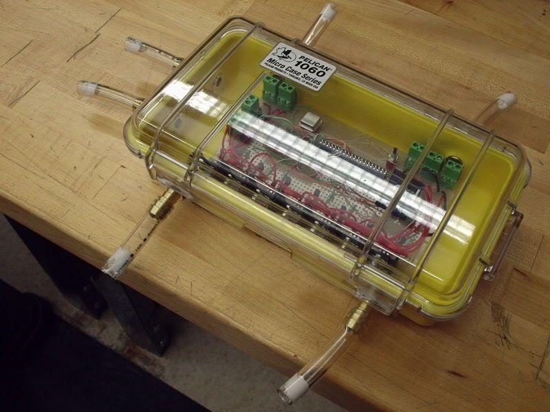
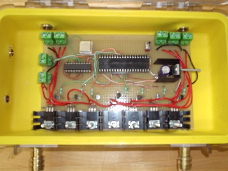
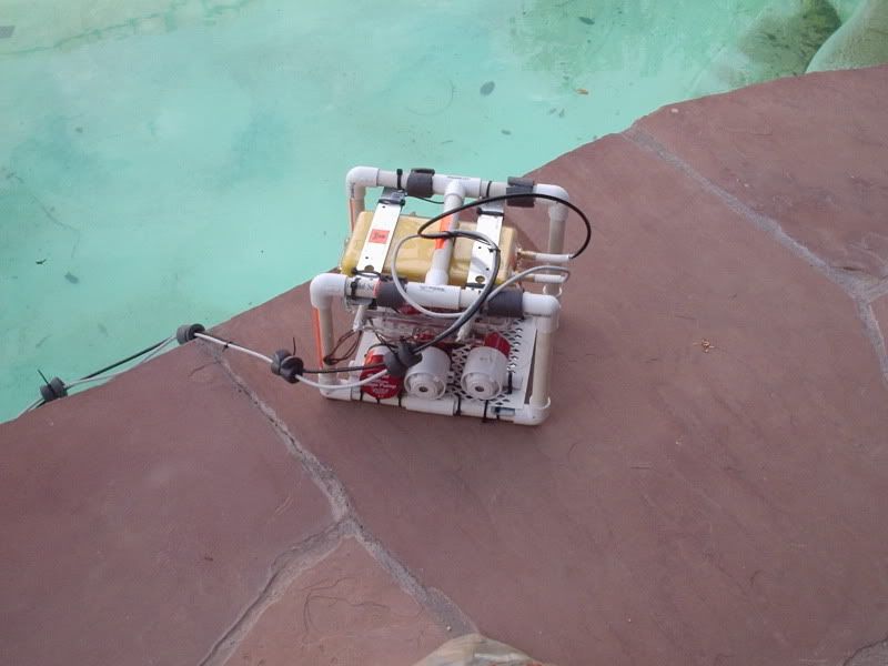
Here the mechanical design revisions are clear. The electronics case is horizontal. The board is mounted to the inside top of the case, where it has some protection from case leaks. The door of the case opens down to drain water when the sub returns to the surface.

The pumps are all mounted laying down on the frame instead of standing. They are much more secure this way and their thrust is put to better use.


Taking another trip around the pool. It is bobing just below the surface. Only the top of the frame and case are above water.
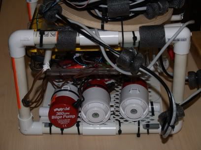
This is close enough to see the three pumps on the left side. The front pump (red cap) is the reverse thrust left side. Two front pumps push the craft in reverse, and two rear pumps push the craft forward. We can 'tank steer' by using one forward pump and the opposite side rear pump.


The other two pumps have their inlets facing out. the center pump is one of the downward facing pumps, which pushes the craft upwards. Rather than having an upwards pump and a downwards pump as we originally planned, we faced both pumps down. This lets the sub sort of puddle hop. We trimmed the sub to slowly sink to the bottom. Then we 'jump' using downward thrust and navigate with forward and reverse thrust.


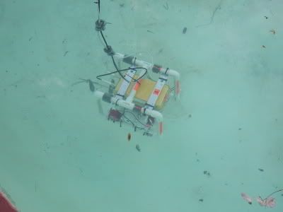
The sub sits on the floor and glides along it pretty well. We did have issues where the pool was highly slanted to go into the deep end. Another problem was that the longer it was in the water, the more affect the leaking had on the boyancy. As air is displaced by water in the case, the boyancy changes and it is harder to get the sub to lift off the bottom and move forward. This could be solved by permanantly sealing the case so that water can not get in.


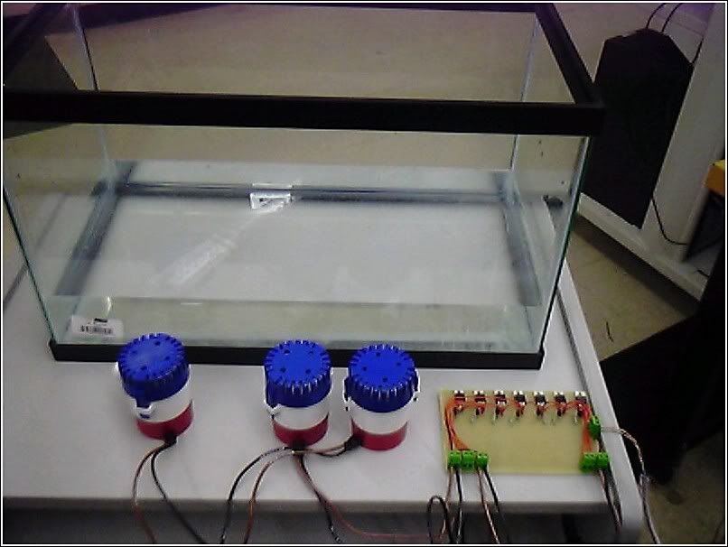
Now that the control software is finalized, this is a possability. At first, the case performed as advertised. We put it in an aquarium with a rock on it for over an hour and it had no leaking.
We then drilled and fitted the hose barbs in order to bring in wiring. These barbs were sealed up with silocone and then plugged. (look in the archive for photos of the process). The water test was repeated and after a few leaks were discovered and mended, again passed for over an hour with no water intrusion.
We believe that constant opening and closing of the case during the design and build process eventually weakened the seal and liner. We believe the gasket as designed is only good for a finite number of uses before it breaks down and fails. That being said, even after 20 mins in the water, there was only about half a cup of water in the case. So the case still performed mostly as advertised, even after our warrenty destruction. Half a cup of water might be fine for a digital camera that is turned off and a wallet, and keychain and other items someone might take with them on a boat trip. It is not ok for an exposed electronics board that is powered up and controlling 6 circuits capable of 5 amps each.
Luckilly the positioning of the board ment that it only got a little wet, and only biased some transistors. In effect, turned on a motor or two when we didnt want them on. This would become apparent when an 'all stop' command was issued and the sub would make a slow spiral.

Tuesday, May 16, 2006

ITTROV - More on the build


This is the sub cage with all of the pumps installed. Warning: a lot of these photos are out of order.


I've been doing a lot of 'coding' lately. I use air quotes only when speaking of the VB side application. :) The code in the sub is written in C.


Ronnie does more soldering. On the page you can see the schematics for the motor control circuits.


About to test the first stage of the electronics. The motor control circuit is built up and those pumps are about to get wet.

Too bad it didn't work! The pumps stayed on and we had no control whatsoever. We built up a test circuit on a breadboard and had the same results. Turned out two of the wires were reversed on all of the circuits. After about 30 minutes of repairs, it worked perfect.


A decent closeup of the electronics inside the case. The pump wires will come in through the brass fittings on the sides. Tubing will be siliconed around the wires to keep out water.

In this shot, the pic micro isnt installed yet.


Gratuitous body shot!

Sunday, May 14, 2006

ITTROV - the sub project (build)


This is Ronnie installing some connections on the electronics system.

Here you can see the frame and pumps.

Closeup of the side of the sub, without the electronics case installed.

Here is the case with the board being test fit.

The tubes on the sides are plugs to test the unit for water tight. When everything is put together, the wires for the umbilical and motors will be threaded through the brass fittings, and will have similar pieces of tubing that are filled with silicone to keep out water.

A close up of the circuit board. Notice the PIC controller chip is not installed. Towards the bottom you can see all the drivers for the motors mounted on heat sinks. The block on the right side with the screw sticking out of it is the voltage regulator for the processor.